Introduction
In a pixel light display, a network is often required to transport large amounts of data to the pixel controllers at high speeds. This can be a significant task if there are many controllers and a high universe count. Poorly designed networks can result in dropped packets and/or unstable connections.
The Problem
In the example shown below, two PixLite E16-S Mk3 controllers are being used to drive a large LED screen. They are both operating on the same network, along with the sending software. Each PixLite is set up to control 96 universes of pixels.

Multicasting without IGMP snooping graphic 1
In this situation, both controllers are receiving all 192 universes, requiring each controller to process all 192 universes to determine whether each is needed. This will then result in a large volume of irrelevant traffic passing through each PixLite’s processor. Consequently, the controller may not be able to keep up with the sheer volume of data, resulting in possible dropped packets and a poor-quality LED screen.
The Solution
Multicasting with a correct network configuration allows the universes to be sent only down the relevant ports on the switch. This is achieved using a networking strategy called Internet Group Management Protocol (IGMP) Snooping.
The example below shows the reduction in traffic for each PixLite.

Multicasting with IGMP Snooping graphic 1
The irrelevant traffic is no longer needing to be processed by the PixLite, so all that remains are the universes that each PixLite needs. This strategy can help avoid each PixLite being flooded with excess data.
What is IGMP Snooping?
When multicasting sACN, each universe of data is sent in a unique multicast group. It is these groups that get transmitted to the network switch. If a pixel controller has subscribed to a group, then the switch transmits that group out the corresponding port.
IGMP Snooping is the process that allows the switch to know which multicast groups each device has subscribed to, only sending the relevant groups to each port. It requires the pixel controller and sending software to operate on an Ethernet protocol that supports multicast (sACN for example). Art-Net does not support multicast traffic delivery. For more information, see the article: Art-Net vs sACN.
Effective IGMP Snooping also requires networking equipment that can support IGMP Snooping for a suitable number of groups and potentially has support for IGMP Querying. If these requirements have been met, a network design can be built that utilizes the benefits of IGMP Snooping and effectively delivers multicast traffic to the correct PixLite controllers. More on selecting suitable network hardware later in this article.
How the switch manages groups
Multicast traffic takes advantage of IGMP to communicate what groups are required for each device. Any device may subscribe to multicast groups. Any device may also query the local network, effectively asking devices to announce the multicast groups they require. However, there is typically only one querier on a network and that would normally be the router, or a network switch configured to send queries.
When a PixLite controller operating on sACN has its Ethernet port initially or re-connected to a network, it will send out IGMP message(s) subscribing to the universes it needs. It will also send out these messages whenever it powers on. These messages are read along the way (“snooped”) by the network switch it is connected to, and the switch will make a note to pass on those universes to that port. Over time, and with multiple controllers, the switch will build up a list of which ports require each multicast group.
This ongoing process is achieved through an IGMP querier. Many network devices can be configured to act as a querier and it is typically a router’s job, but it may also be assigned to a network switch, as mentioned above. Often lighting networks are isolated and operate without a connection to a wider network, so they may not have a router to perform this function. In this case, you will probably need to elect one of the network switches to act as the IGMP querier (not all switches have this ability). The querier device will periodically broadcast a message to every device on the network, asking who needs which multicast group. Each device that needs a group will reply with a request to subscribe to that multicast group. The timing of these queries will depend on the network configuration, but a suggested value is at least twice as frequent as the IGMP timeout value.
Network Switch Selection
Switches come in many shapes, sizes, and prices. For a large lighting display that uses IGMP Snooping, you’ll need to get the right one(s). The first characteristic to look for is a managed switch. Managed switches are configurable through a browser, similar to how a router might be configured. Unmanaged switches do not need this configuration and are designed to work without needing setup. A managed switch will allow configuration of IGMP Snooping, IGMP Querying, VLAN set up, and much more. Therefore, you must have a managed switch if you’re using IGMP Snooping.
Most managed switches will support IGMP Snooping, but you should double check this for the one you choose.
Managed switches also come in multiple physical sizes, with varying numbers of Ethernet ports. To determine which managed switch is best for your application, you’ll need to consider how many multicast groups will you be needing the switch to forward to your pixel controllers. A managed switch will have a limitation on how many multicast groups it can support, which will be specified by the manufacturer. This limit will not necessarily increase as you increase the number of physical ports. A common limit for smaller managed switches is 128 groups. If more groups are delivered to the switch than it can support, then it will either broadcast the excess packets to all ports, or it will drop them, depending on how you choose to configure it. This is a significant consideration to make, as it has the potential to either lose packets completely, or flood your PixLite with more universes than it can handle.
In the first example below, a single switch is used, IGMP Snooping is enabled, and excess groups are set to broadcast. Both PixLite’s now receive more incoming data than they can handle. Even if the setting is changed to drop these excess incoming packets, the design would be flawed, as it would then stop those packets from arriving at the correct PixLite.
One method for overcoming this limitation is by utilizing multiple switches in a core/edge configuration. The core switch receives and forwards all multicast groups from the sending software. Then the edge switches receive all multicast groups from the core switch but drop the excess packets that the connected pixel controllers do not need. This is shown in the second example, where the edge switches do not exceed their multicast group limit, and they can deliver all relevant universe to their connected PixLite.

IGMP Snooping graphic 1
This is a simplified illustration. In practice you would of course have multiple PixLite controllers running off each edge switch. However, the total number of universes consumed by the PixLite devices on each edge switch must be within the multicast group limit for the switch.
In this example, there is no router on the network that can act as an IGMP Querier, and so a switch should instead be used for this role. Only one switch should be set up in this way, as only one querier is needed. The most sensible choice for this role is the core switch and enabling this feature will be discussed later.
Configuring the Network for IGMP Snooping
Once you have selected network equipment that meet the requirements, you need to configure the relevant features.
Firstly, you need to enable IGMP Snooping. On the core switch (if you have one according to the above diagram), IGMP Snooping can be disabled. On the edge switches, you need to enable IGMP Snooping. An example of this setting on a Cisco SG300-52 model switch is shown below.

IGMP Snooping graphic 2
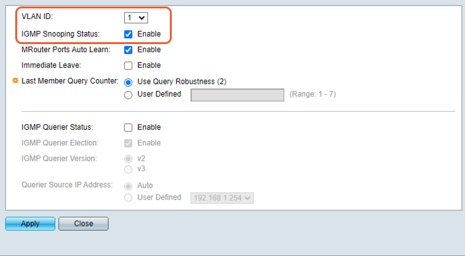
This particular switch has been set up with 6 VLANs and requires IGMP Snooping to be enabled globally (above), and then for each VLAN as required (below).

IGMP Snooping graphic 3
There will also be an option for what happens if there are more multicast groups than the switch can handle. The switch can be configured to drop or broadcast these additional groups. It is possible that the edge switch receives more multicast groups in, than it is sending out. Even though the incoming number of groups exceeds the IGMP Snooping limit, if the number of output IGMP groups are controlled, the edge switch can simply be configured to drop the excess incoming packets. An example of this setting on a Cisco SG300-52 model switch is shown below. This switch is a 52-port switch and requires this setting to be configured per port. Ports 1 – 24 (1) are configured to filter excess incoming packets, which is typical for an edge switch; and Ports 25 – 52 (2) are configured to forward excess incoming packets, typical for a core switch.

IGMP Snooping graphic 4
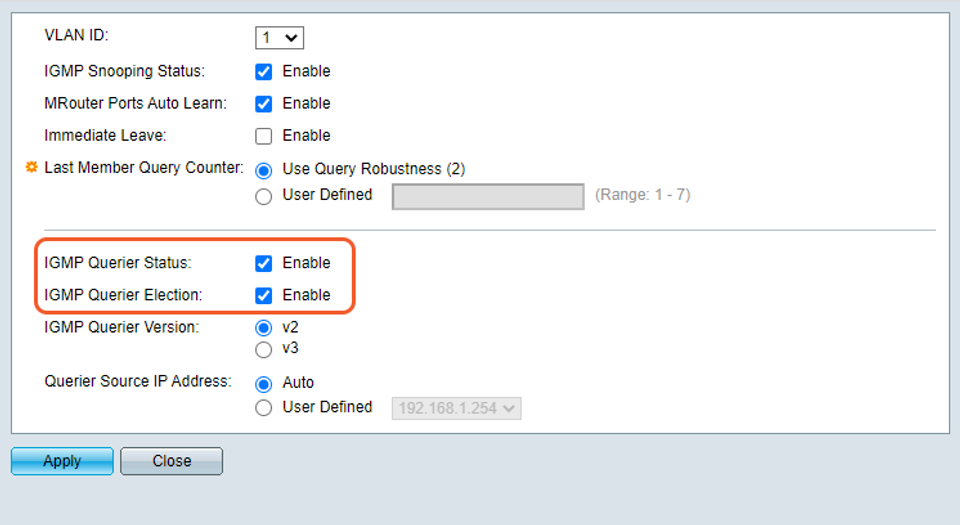
Finally, one of your network switches may need to be configured as the IGMP querier (as described earlier). An example of this setting on a Cisco SG300-52 model switch is shown below. This switch requires a global setting to be enabled, as well as each VLAN, similar to how it enables IGMP Snooping.

IGMP Snooping graphic 5
For detailed instructions on configuring these options, relevant documentation from the network equipment manufacturer should be consulted.