Introduction
Note: This feature is not available on “E” series controllers.
With Advatek’s 3rd generation of pixel control firmware, PixLite® devices with dual gigabit Ethernet ports allow Ethernet loop-through and redundant network topologies. Combined with the critically important Universe Data Hardware Firewall, controllers can be reliably daisy chained without worrying about latency and performance problems which are normally encountered in a daisy chain topology.
These features, along with a host of others included as part of the Mk3 processor, provide incredible, scalable value for any lighting project. This means you need fewer Advatek controllers to control the same number of pixels, making Advatek’s new Mk3 processor the best choice for your pixel lighting application.
Physical Connections
Each of the dual gigabit Ethernet ports are connected internally by dedicated Ethernet switch electronics on board the PixLite® controller. This means that both ports act together as a 2-port gigabit network switch. If only one PixLite® is being used, then either port can be connected to the computer or network switch to allow communication and data transmission. However, PixLite® Mk3 devices shine when working with multiple pixel controllers.
The following examples show some of the configurations that are possible with Ethernet loop-through. The dual gigabit Ethernet ports are used to connect multiple PixLite® controllers together and even external Ethernet hardware.

Daisy chained pixel controller graphic

Daisy chained pixel controller graphic 2

Daisy chained pixel controller graphic 3
How to Create a Redundant Network Loop
The dual gigabit Ethernet ports can be used to simply connect a redundant Ethernet cable between the switch and each PixLite® (assuming STP has been enabled - see below). Alternatively, a network loop can be created with multiple PixLite® Mk3 devices, to combine the security of redundancy with the simplicity of Ethernet loop-through.
At the end of a line of daisy chained PixLite® Mk3 devices, an extra network cable can be used to create a redundant loop topology. Simply connect one end to the unused Ethernet port on the last PixLite®, and the other end to a compatible network switch.
An example of this is shown below.
Note: the switch will need to be selected and configured as per the next two sections.

Daisy chained with redundant network loop graphic
The advantage of a redundant network loop is that if there is a single point of failure (a controller, cable, or power supply), there is still a valid path for network traffic to follow. This means the other controllers can keep running! Faults typically occur from a network cable being disconnected or damaged. For installations where a large number of PixLite® controllers are daisy chained together, the redundant link is a cheap and easy insurance policy to help mitigate a potential failure in the network cabling.
An example situation is shown below. A fault is detected by the network switch, which then activates the port that the redundant line is connected to. Arrows are shown to indicate connectivity between the switch and the pixel controllers.

Example of redundancy during fault graphic
Selecting a Network Switch
Not all switches are capable of performing the required management of network traffic that redundant network loops rely on. Any network switch that supports Spanning Tree Protocol (STP) will be able to achieve a redundant network loop topology. If a redundant Ethernet link is to be used with PixLite® Mk3 pixel controllers, then STP must be supported and enabled within the network switch. Any managed network switch is likely to have this feature, but you should confirm this with the vendor.
Network devices will only work properly when a single active path between two devices exist. If a network loop is improperly created, then there may be multiple paths the network data can take – this will either cause the network to quickly become unstable, or the switch may even deactivate these ports entirely, to protect the rest of the network.
To eliminate undesired loops, the network switch will automatically determine if any ports on the switch end up connected back to each other (forming a loop). If a loop is found, then the network switch will only activate one port, creating a single-path link. Any other ports that are determined to be connected in the loop will be set to standby. The switch continues to monitor if a loop is present. If the loop is found to be no longer connected, then the switch will activate the second port that was previously on standby. The process repeats and the second port is disabled automatically once the loop is reformed. This is how the redundant network topology creates resilience against faults.
Configuring STP in a Network Switch
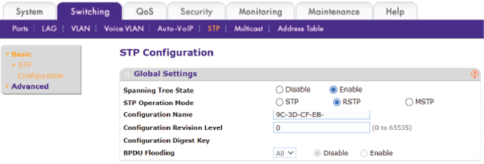
STP may not be enabled by default in your network switch. Most network switches will allow basic or advanced configuration of STP. In this example, a NETGEAR GS108T switch will be configured to enable STP with basic settings.

STP configuration graphic
In most cases, no advanced configuration will be required and simply enabling STP will be enough. If Rapid Spanning Tree Protocol (RSTP) is available, we recommend using that instead of STP, as it will respond faster to changes in the network topology. To explore advanced STP settings, such as bridge priority, bridge timing, maximum STP hops etc, consult the user documentation of your network switch.
How Many can be Connected Together?
The beauty of Ethernet loop-through in PixLite® Mk3, is that the high speed of gigabit communication, as well as the robustness of the Universe Data Hardware Firewall combine together to create a system that isn’t bound by the latency and performance problems which are normally encountered in a daisy chain topology.
With PixLite® Mk3, latency due to daisy-chaining can be ignored in any practical installation. The number of pixel controllers that can be connected together is practically unlimited.